Difference between revisions of "SSR4 DMX ONLY Manual"
(New page: ='''Adding the optional DMX to the SSR4 '''= == Parts List DMX Option == {| class="prettytable" | '''Mouser Part #''' | '''Description''' | '''Quantity''' |- |294-15K-RC |1W 5% Carbon ...) |
(typo) |
||
| Line 111: | Line 111: | ||
| − | Open | + | Open your bag of DMX parts and find the chip sockets. You should have no problem finding the location for these on the board so make sure to put them in the correct direction and solder them in. |
| Line 124: | Line 124: | ||
Install the one .1 uf cap next to the large socket. | Install the one .1 uf cap next to the large socket. | ||
| − | |||
=='''Step 2'''== | =='''Step 2'''== | ||
Revision as of 21:56, 26 September 2009
Contents
Adding the optional DMX to the SSR4
Parts List DMX Option
| Mouser Part # | Description | Quantity |
| 294-15K-RC | 1W 5% Carbon Film Resistors 15Kohms 5% | 2
|
| 571-1-390261-1 | IC Sockets 6P ECONOMY TIN | 2
|
| 649-65474-002LF | Bergcon Connectors SHUNT TIN | 2
|
| 140-XRL25V100-RC | Radial Electrolytic Capacitors 25V 100uF 20% | 1
|
| 299-120-RC | 1/8W 5% Carbon Film Resistors 120ohms 0.05 | 1
|
| 299-22K-RC | 1/8W 5% Carbon Film Resistors 22Kohms 0.05 | 1
|
| 511-L7805ACV | Voltage Regulators 5.0V 1.0A Positive | 1
|
| 511-ST485BN | 5V RS-485 Interfaces Hi-Spd Lo Pwr Trans | 1
|
| 538-22-03-2021 | .100 K.K. Connectors VERT PCB HDR 2P TIN PLATING | 1
|
| 538-22-03-2031 | .100 K.K. Connectors VERT PCB HDR 3P TIN PLATING | 1
|
| 571-1-390261-2 | IC Sockets 8P ECONOMY TIN | 1
|
| 571-1-390261-5 | IC Sockets 18P ECONOMY TIN | 1
|
| 571-5520260-4 | Modular Jacks 8P8C TOP ENTRY | 1
|
| 579-PIC18F1220-I/P | PICmicro - PIC18Fxxx Flash MCUs 4KB 256 RAM 16 I/O | 1
|
| 581-SA105E104Z | Axial Ceramic Capacitors 50volts 0.1uF Z5U | 1
|
| 782-H11AA1 | Optocouplers Bi-Directional Input | 1
|
| 673-020-5370-0 | Encapsulated Transformers 0.5 VA 6V@83mA | 1
|
| 647-UHE1C681MPD | Low Impedance Aluminum Electrolytic Capacitors - 680uF 16V | 1
|
| 621-DF005M | Rectifier - Bridge 1.0A 50V | 1
|
Step 1
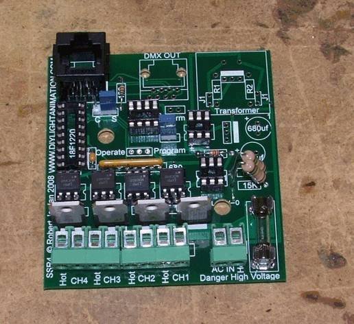
Open your bag of DMX parts and find the chip sockets. You should have no problem finding the location for these on the board so make sure to put them in the correct direction and solder them in.
Now find the 120 ohm resistor and locate it place between the locations for the two RJ45 jacks and install it.
Find the 22K resistor and install it in its place between the two 6 pin sockets.
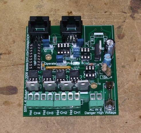
Install the two large 15K resistors in their place above the fuse. You will stand these up as in the picture. Make sure they do not touch anything else as they carry 120 volts when live.
Install the one .1 uf cap next to the large socket.
Step 2
Install the two capacitors (680uf & 100uf) just above the large 15K resistors.
Install the 7805 5 volt regulator to the right of them with the metal side facing the capacitors.
Install the 2 terminal pin jumper in the location marked TERM. And the 3 terminal pin jumper in the location marked operate/program.
Install the second RJ45 jack in its location.
Step 3
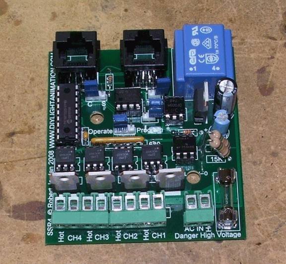
Install the Transformer on the board. It will only fit one way and you can ignore the markings under it as they are for optional parts for non 120 volt operation.
Now we need to put the chips in. As before take your time. There are two 6 pin chips make sure the one with the + - on the top of it is put near the Transformer and the + - side is lined up with the + - markings on the pcb.
Make sure these chips are inserted in the correct direction. Now set you jumpers as shown above to make it a Controller.
BE SAFE!
Thank you, enjoy your Controller and
MAY GOD BLESS YOU IN ALL YOU DO!


