Difference between revisions of "Using a LOR iDMX adapter to drive Lynx equipment."
From DiyLightAnimation
m (Clarification on the IDMX-1000 XLR connectors.) |
|||
| (2 intermediate revisions by one other user not shown) | |||
| Line 2: | Line 2: | ||
[[Image:LOR_iDMX.jpg]] | [[Image:LOR_iDMX.jpg]] | ||
| + | |||
The image is from Light-O-Rama. | The image is from Light-O-Rama. | ||
| + | |||
The following are the pinouts, assuming TIA-568B for the RJ45 end. | The following are the pinouts, assuming TIA-568B for the RJ45 end. | ||
| − | * | + | |
| + | * To connect to Lnyx Equipment | ||
** XLR Pin 1 (GND) ----> N/C | ** XLR Pin 1 (GND) ----> N/C | ||
** XLR Pin 2 (-ve) ----> RJ45 Pin 2 (Orange) | ** XLR Pin 2 (-ve) ----> RJ45 Pin 2 (Orange) | ||
** XLR Pin 3 (+ve) ----> RJ45 Pin 1 (White/Orange) | ** XLR Pin 3 (+ve) ----> RJ45 Pin 1 (White/Orange) | ||
| + | |||
| + | |||
| + | * To connect to Light-O-Rama Equipment | ||
| + | ** XLR Pin 1 (GND) ----> N/C ? | ||
| + | ** XLR Pin 2 (-ve) ----> RJ45 Pin 5 (White/Blue) | ||
| + | ** XLR Pin 3 (+ve) ----> RJ45 Pin 4 (Blue) | ||
| + | |||
| + | |||
| + | Do not use the DMX IN connector. This is used for connecting to an existing DMX network and is terminated independately from the DMX out connector network. | ||
Latest revision as of 13:18, 14 July 2011
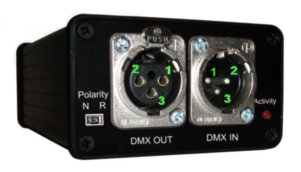
If you are using a Light-O-Rama iDMX adapter to drive Lynx equipment, your XLR to RJ-45 adapter should look like this.
The image is from Light-O-Rama.
The following are the pinouts, assuming TIA-568B for the RJ45 end.
- To connect to Lnyx Equipment
- XLR Pin 1 (GND) ----> N/C
- XLR Pin 2 (-ve) ----> RJ45 Pin 2 (Orange)
- XLR Pin 3 (+ve) ----> RJ45 Pin 1 (White/Orange)
- To connect to Light-O-Rama Equipment
- XLR Pin 1 (GND) ----> N/C ?
- XLR Pin 2 (-ve) ----> RJ45 Pin 5 (White/Blue)
- XLR Pin 3 (+ve) ----> RJ45 Pin 4 (Blue)
Do not use the DMX IN connector. This is used for connecting to an existing DMX network and is terminated independately from the DMX out connector network.
