Difference between revisions of "Mod Wireless"
(→Directions: Rewrite for clarity) |
|||
| Line 8: | Line 8: | ||
==Directions== | ==Directions== | ||
| − | + | Purchase an 8-pin DIP header (Mouser PN# 535-08-600-10, Digikey A101-ND). | |
| + | Build the EX/RX as usual, but do not solder on the two 4-pin headers normally used to connect it to the Lynx. | ||
| − | + | Solder three wires (stranded wire, about 24 or 26AWG) to pins 1, 5, and 8 of the adapter. If you have a spare IC socket, it's helpful to plug the DIP header in it before soldering the wires so the pins don't move around too much while you are soldering. | |
| − | + | Attach the other ends of the wires as shown in the attached picture. Insert the wires into the holes where the 4-pin headers would normally go. | |
| − | Presto! | + | Remove the RS485 transceiver (MAX485, SN75176 or similar) from the board that you are converting to wireless. Plug the DIP header in its place, making sure that pin 1 on the header is plugged in to pin 1 on the socket. |
| + | |||
| + | Figure out where to mount the EX/RX. Pick a place where the EX/RX won't come into any contact with any metal (PC boards, parts, case); use an insulating plastic sheet if needed. The wireless module on the EX/RX should be located away from any metallic items to avoid limiting the receive range. Clean the mounting area and back of the EX/RX with some isopropyl (rubbing) alcohol. Use some good quality double-sided foam tape to stick the EX/RX to the case. | ||
| + | |||
| + | Presto! You now have $20 wireless in these devices. | ||
[[Image:Ex_rx_mod.jpg]] | [[Image:Ex_rx_mod.jpg]] | ||
Revision as of 09:11, 10 June 2011
This Modification is for connecting up the Lynx Express Wireless Module (EX/RX) to other Controllers instead of using the stand alone receiver.
Currently Applies to the Following Controllers:
- Freestyle
- MR-16
- SSR4-DMX
- possible other controllers but its untested
Directions
Purchase an 8-pin DIP header (Mouser PN# 535-08-600-10, Digikey A101-ND). Build the EX/RX as usual, but do not solder on the two 4-pin headers normally used to connect it to the Lynx.
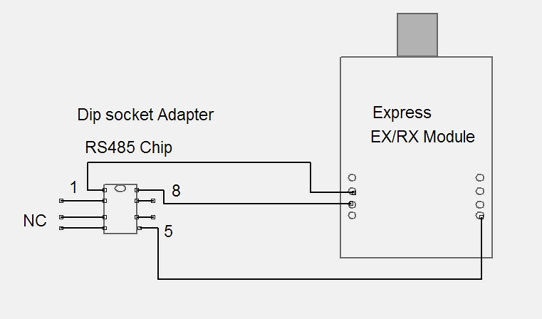
Solder three wires (stranded wire, about 24 or 26AWG) to pins 1, 5, and 8 of the adapter. If you have a spare IC socket, it's helpful to plug the DIP header in it before soldering the wires so the pins don't move around too much while you are soldering.
Attach the other ends of the wires as shown in the attached picture. Insert the wires into the holes where the 4-pin headers would normally go.
Remove the RS485 transceiver (MAX485, SN75176 or similar) from the board that you are converting to wireless. Plug the DIP header in its place, making sure that pin 1 on the header is plugged in to pin 1 on the socket.
Figure out where to mount the EX/RX. Pick a place where the EX/RX won't come into any contact with any metal (PC boards, parts, case); use an insulating plastic sheet if needed. The wireless module on the EX/RX should be located away from any metallic items to avoid limiting the receive range. Clean the mounting area and back of the EX/RX with some isopropyl (rubbing) alcohol. Use some good quality double-sided foam tape to stick the EX/RX to the case.
Presto! You now have $20 wireless in these devices.
