Manual Slave
Contents
Introduction
Thanks for deciding to build the Lynx Slave. I hope that you will find both the build and the use of the device to be a pleasurable experience. The Slave is a piece of hardware that has required many hundreds of hours to create. While the hardware is basic, the software that operates it is complex with many possible issues for the developer to overcome. The Slave requires a Lynx EtherDongle as it is simply an add-on to the EtherDongle which allows the two to be much more than either one is alone.
Enjoy
RJ
Preparing to Build
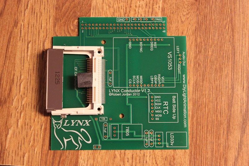
I trust you found everything in your order, but should you have any issue just contact your coop manager and they will take care of it.
The PC Board you received should already have compact flash connector on it.
The next thing we want is to make sure you are up to speed on soldering and electrostatic protection of the components in your kit. If you are not an experienced printed circuit builder I recommend you visit the site:
http://curiousinventor.com/guides/How_To_Solder
And check out their extremely good video on soldering correctly. Even if you are an expert it is a good video to watch.
Another issue you must be aware of is that some electronic components can be damaged easily by electrostatic charges that can build up in you or your equipment. We have all been shocked by walking on carpet and grabbing a door knob before. This is electrostatic charge in action. It takes much less than this to hurt some of our parts. If you are unfamiliar with procedures to protect from this please use the internet to research it before opening your parts up. You can damage your parts with improper handling!
You will need a few tools that do not come with your kit to build the Slave. You will need a good soldering iron. I can not stress enough that a good soldering iron makes a big difference in these projects. The little 15w cheap irons are more apt to hurt your parts by taking too long to get the parts up to soldering temperature than a good iron which can bring it up to temp very fast. Remember it is more how long you keep the part hot than it is how hot you get it within reasonable soldering temperatures. A good soldering iron can be had for very reasonable amounts of money. You can purchase one for $30 to $60 dollars. Most anything that is called a soldering station where there is a temperature control separate from the iron itself will more than likely be fine but make sure it is rated for more than 15 watts. I myself use a cheap Weller like this one
Solder Stations:
It works fine and is very inexpensive. I even saw this model on sale at Sears. Radio Shack has a very nice looking Digital Soldering Station (Model #64-053) for sale but you can't order the tips directly from Radio Shack. You need to order them directly from the manufacturer at Madell Tech's website. A forum member uses this iron at his business and on the road and it's been rock solid.
Another recommended Solder Station is the MPJA 302A is has a digital temperature readout
- http://www.mpja.com/prodinfo.asp?number=15141+TLMPJA Model 302A
What ever you get make sure and get 4 - 5 extra tips for it. It is an opinion thing but I prefer and find most prefer Chisel tips. get a couple .8 and a few 1.6 to see which you like and then you are ready to go. The tips do wear out and need replacement from time to time. I can build maybe 4 to 8 big controllers (FS, Etc) with a single tip but when you are learning you will use them up faster.
You need solder so buy some. I recommend .032 size (0.8mm or 0.7mm) as the larger sizes tend to cause you to put too much solder on. How much? Go ahead and get a 1 lb spool as it’s cheaper in large volume and you will go through it faster than you think. Make sure you are getting rosin core for electronics, they make some solder for plumbing that has acid as the core this is a bad mistake to make.
You need some work area to work with good lighting. Do not attempt to solder circuit boards in poorly lighted areas. If you wear reading glasses go get them you will want them I promise you. I recommend a set of helping hands like this: [1] Radio Shack or [2]
HarborFreight or [3] Amazon.com
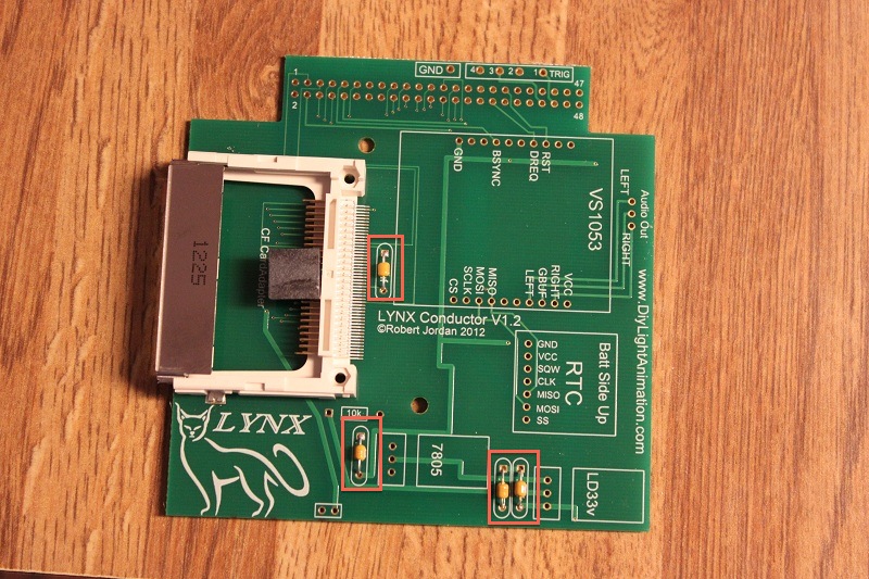
Step 1 - Capactors
- Install the four .1uf capacitors as shown above. Solder and trim them.
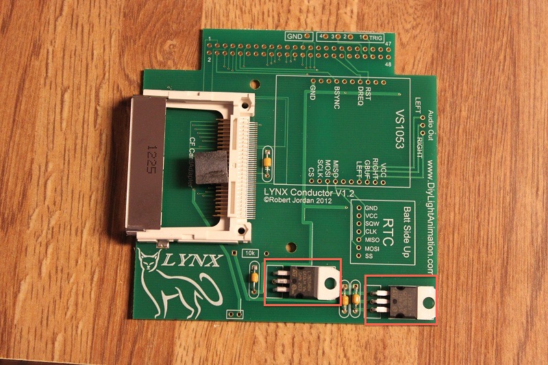
Step 2 - Voltage Regulators
- Install the 5v regulator p/n 7805 and the 3.3v regulator p/n 1117v3.3. Ensure you install them in the correct locations as marked on the PCB as they look exactly the same.
- Start by bending the legs 90 degrees away from the body to allow you to insert them flush with the PCB. Trim the legs after soldering them.
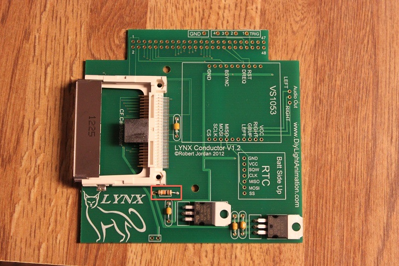
Step 3 - Resistor
- Install the 10k resistor right beside the card socket. Solder and trim.
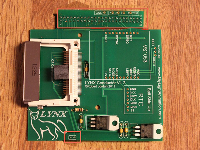
Step 4 - Double Row Header & Power Pins
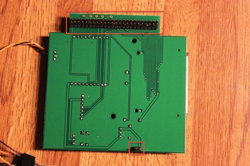
- Install the two 12 x 2 pin headers into the PCB making sure they are pointing down. The shorter side of the pins are into the PCB and they are pushed flush with the PCB all the way across.
- Install 2 pin header opposite side the 12 pin header
- They are made to fit a little tight for this purpose. This is important, as you do not want them out of alignment when you try to install the Slave on the EtherDongle.
- Solder it into place and then repeat with the two pin header on the other end of the PCB.
Step 5 - CF Socket Ejector
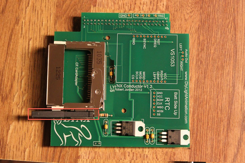
- Install the ejecting unit onto the card socket. If the little plastic tab is still on your socket slide it off of the pins and discard it.
- Align the ejector over the socket and find the tabs with the square holes in the ejector. Tilt the ejector to put the two small points on the socket that lock into the tabs.
- Then rock the other side down until it snaps on the other side.
Step 6 - Finish & Attach to EtherDongle
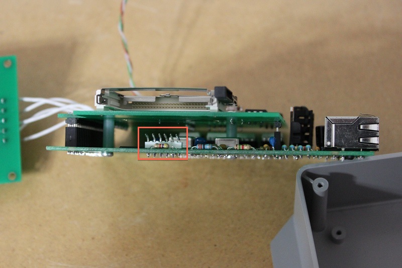
- NOTE: If you have straight pins on your EtherDongle ICSP connector then they have to be either bent to a 90 degree angle or replace it with this ICSP Header from Mouser.
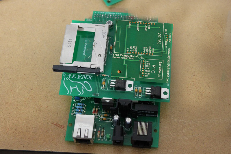
- To install the Slave onto your EtherDongle just push the two 4-40 x 3/4 bolts up through the EtherDongle from below so the heads are on the bottom of the PCB. Then slide the two spacers on the bolts.
- Plug your Slave PCB into the EtherDongle and push the bolts up into the holes that line up on the Slave.
- Start the nuts and tighten very lightly. Do not over tighten. It should just be holding lightly down.
Programming The Lynx EtherDongle
In order to program the Lynx EtherDongle you must use the PICKIT3.
Connect the PICKIT3 to the computer via the USB cable. Plug in the PICKIT3 to the EtherDongle ICSP header, making sure you match the triangle marks on both the PICKIT3 and the EtherDongle board.
Start the PICKIT3 programming application. Select "PIC32MX795F512L" from the "Device:" drop down list. Select "File" from the tool bar and select "Import". Navigate to the location of the downloaded firmware and select the Slave/EtherDongle PixelNet or DMX .hex file. Click on the write button and once it completes, you may also press the "verify" button.
