Manual EtherDongle
NOTE: DON'T USE THE 49.9K RESISTORS FROM THE FIRST COOP, RJ IS GETTING REPLACEMENTS. THEY SHOULD BE 49.9 OHM
If you do have the 49.9k resistors from the first coop pm RJ for replacement instructions
Contents
- 1 Introduction
- 2 Preparing to Build
- 3 Step 1 - Installing the Resistors
- 4 Step 2 - Installing more Resistors
- 5 Step 3 - Installing the 0.1 uF Ceramic Capacitors
- 6 Step 4 - Installing the 10uF Ceramic Capacitors
- 7 Step 5 - Installing the IC Sockets
- 8 Step 6 - Installing the DC/DC Convertor
- 9 Step 7 - Installing the Headers
- 10 Step 8 - Installing LED and Voltage Regulators
- 11 Step 9 - Installing the Voltage Regulator Heat Sink
- 12 Step 10 - Installing the Ethernet, Power Connector, and RJ45 Jack
- 13 Step 11 - Installing the Electrolytic Capacitors and Oscillators
- 14 Step 12 - Installing the IC Chips
- 15 Programming The Lynx EtherDongle
Introduction
Thank you for making the decision to build the LYNX EtherDongle. I believe this decision will be one you will be very happy with.
The EtherDongle is not really one thing. In its most basic form it is a device that, with the correct firmware loaded, takes information in the form of E1.31DMX over Ethernet protocol and provides either 2048 channels of DMX ( 4 Universes ) out, or 16384 channels of PixelNet ( 4 Universes ).
It can also be a development device to design other systems with just the use of new firmware.
It accepts daughter boards that plug in that anyone can design using the information that will be provided. This allows you to add new capabilities to it.
Before we start assembly of the EtherDongle we want to do two things. First we need to take inventory and make sure we have all the components that should have come with the coop kit or Mouser order. Please use static precautions in the handling of sensitive parts. If you are not familiar in them please research on the Internet prior to handling them. You can damage your parts with improper handling!
TAKE YOUR TIME BUILDING THE ETHERDONGLE. Take care inspecting the solder joints and making sure ALL parts and chips are in the proper orientation as per the silk screen on the PCB.
Preparing to Build
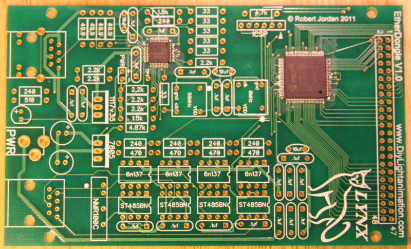
I trust you found everything in your order, but should you have any issue just contact your coop manager and they will take care of it.
The PC Board you received should already have two surface mount chips installed on it. All of the components you will be installing are through-hole so no surface mount work will be required.
The next thing we want is to make sure you are up to speed on soldering and electrostatic protection of the components in your kit. If you are not an experienced printed circuit builder I recommend you visit the site:
http://store.curiousinventor.com/guides/How_to_Solder
And check out their extremely good video on soldering correctly. Even if you are an expert it is a good video to watch.
Another issue you must be aware of is that some electronic components can be damaged easily by electrostatic charges that can build up in you or your equipment. We have all been shocked by walking on carpet and grabbing a door knob before. This is electrostatic charge in action. It takes much less than this to hurt some of our parts. If you are unfamiliar with procedures to protect from this please use the internet to research it before opening your parts up. You can damage your parts with improper handling!
You will need a few tools that do not come with your kit to build the ETHERDONGLE. You will need a good soldering iron. I can not stress enough that a good soldering iron makes a big difference in these projects. The little 15w cheap irons are more apt to hurt your parts by taking too long to get the parts up to soldering temperature than a good iron which can bring it up to temp very fast. Remember it is more how long you keep the part hot than it is how hot you get it within reasonable soldering temperatures. A good soldering iron can be had for very reasonable amounts of money. You can purchase one for $30 to $60 dollars. Most anything that is called a soldering station where there is a temperature control separate from the iron itself will more than likely be fine but make sure it is rated for more than 15 watts. I myself use a cheap Weller like this one
Solder Stations:
It works fine and is very inexpensive. I even saw this model on sale at Sears. Radio Shack has a very nice looking Digital Soldering Station (Model #64-053) for sale but you can't order the tips directly from Radio Shack. You need to order them directly from the manufacturer at Madell Tech's website. A forum member uses this iron at his business and on the road and it's been rock solid.
Another recommended Solder Station is the MPJA 302A is has a digital temperature readout
- http://www.mpja.com/prodinfo.asp?number=15141+TLMPJA Model 302A
What ever you get make sure and get 4 - 5 extra tips for it. It is an opinion thing but I prefer and find most prefer Chisel tips. get a couple .8 and a few 1.6 to see which you like and then you are ready to go. The tips do wear out and need replacement from time to time. I can build maybe 4 to 8 big controllers (FS, Etc) with a single tip but when you are learning you will use them up faster.
You need solder so buy some. I recommend .032 size (0.8mm or 0.7mm) as the larger sizes tend to cause you to put too much solder on. How much? Go ahead and get a 1 lb spool as it’s cheaper in large volume and you will go through it faster than you think. Make sure you are getting rosin core for electronics, they make some solder for plumbing that has acid as the core this is a bad mistake to make.
You need some work area to work with good lighting. Do not attempt to solder circuit boards in poorly lighted areas. If you wear reading glasses go get them you will want them I promise you. I recommend a set of helping hands like this: [1] Radio Shack or [2]
HarborFreight or [3] Amazon.com
Step 1 - Installing the Resistors
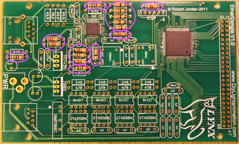
Install the first set of resistors in their proper place. Resistors do not have a wrong direction but I always put the color bands facing the same direction to make it look professional.
Install six 2.2K ohm (red-red-red) resistors.
Install six 33 ohm (orange-orange-black) resistors.
Install one 510 ohm (green-brown-brown) resistor on the left side.
Install one 4.7K ohm (yellow-violet-red) resistor in the upper right.
Install two 1.5K ohm (brown-green-red) resistors.
Solder all these resistors and trim the leads. You should have 16 resistors installed now.
Step 2 - Installing more Resistors
NOTE: DON'T USE THE 49.9K RESISTORS FROM THE FIRST COOP, RJ IS GETTING REPLACEMENTS. THEY SHOULD BE 49.9 OHM
If you do have the 49.9k resistors from the first coop pm RJ for replacement instructions
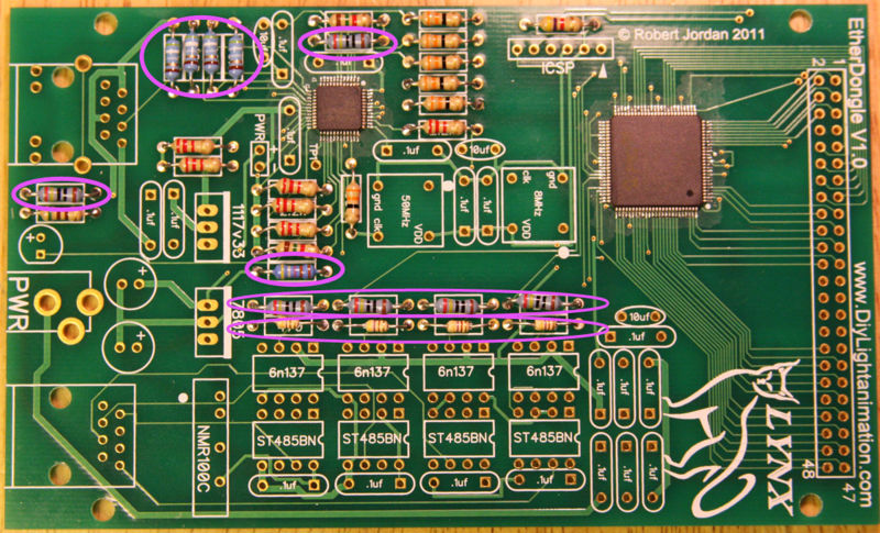
Install the final set of resistors in their proper place.
Install four 470 ohm (yellow-violet-black-black-brown) 1% resistors in a row near the middle.
Install six 240 ohm (red-yellow-brown) 5% resistors, 4 in a row near the middle, 1 near the top, and 1 on the left.
Install four 49.9 ohm (yellow-white-white-gold-brown) 1% resistors in the upper left corner.
Install one 4.87K ohm (yellow-gray-violet-brown-brown) 1% resistor.
Solder all these resistors and trim the leads. You should have a total 31 resistors installed now.
Step 3 - Installing the 0.1 uF Ceramic Capacitors
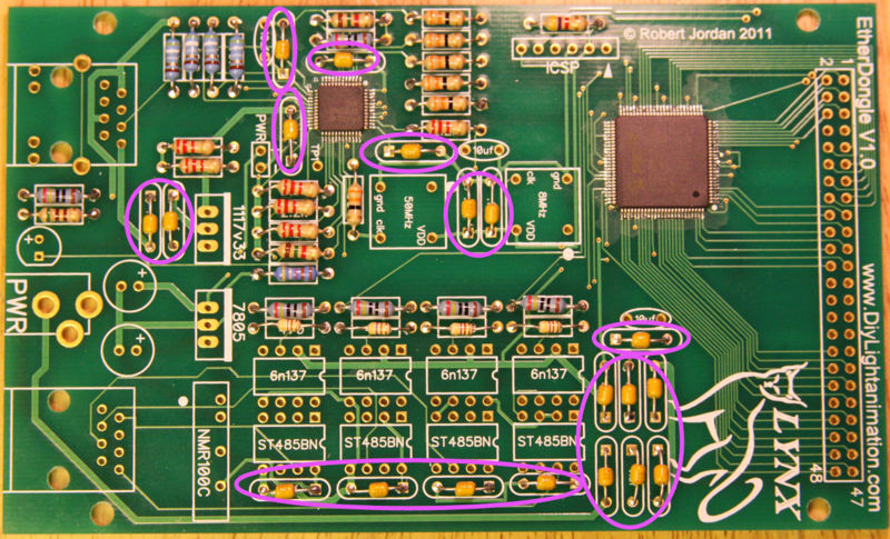
Install nineteen 0.1uf capacitors in their proper location on the board. There is no wrong direction for these.
Solder all these capacitors and trim the leads.
Step 4 - Installing the 10uF Ceramic Capacitors
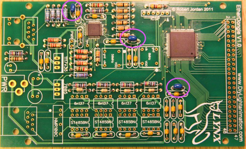
Install three 10uf capacitors in their proper location on the board. There is no wrong direction for these.
Solder the capacitors and trim the leads.
Step 5 - Installing the IC Sockets
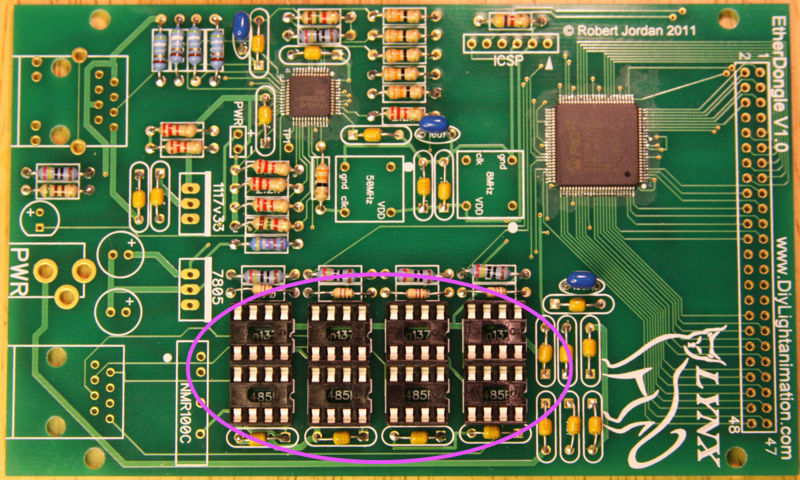
Install the eight 8 pin IC sockets in the middle lower section of the board.
Line up the notch on the socket with the notched end of the drawing on the PCB and then solder all the pins.
Some sockets now come with slightly contoured pins that hold them in place in the PCB prior to soldering. If you do not have this kind of socket you will want to use a method to hold it in place while soldering. Everyone has their own way of holding the socket in. I like to turn the board over to the back and put the least amount of solder I can over one of the middle holes on one side of the socket. This allows you to put the pins of the other side of the socket through and hold the socket while pushing extremely easy. Then you heat that one hole on the back. When the solder melts the socket will drop in. remove the iron and it will cool and hold the socket in until you are done. Make sure to reheat this pin while doing the others to insure you have a good joint. Some people prefer to use tape to hold them in and some even super glue them on first and then solder. If you use tape then the painter’s masking tape is a good option as it does not leave any residue behind when it is removed. Make sure your socket is in the correct holes and that it faces the correct way and then solder the other pins in.
Step 6 - Installing the DC/DC Convertor
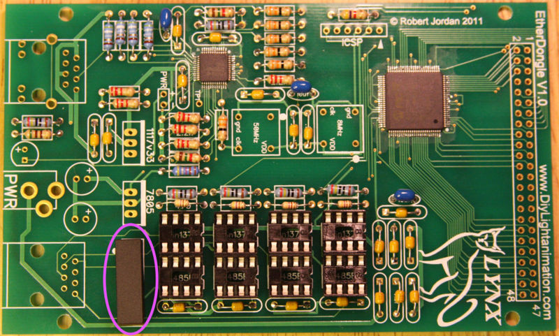
Install the black rectangular DC/DC convertor in the location labeled NMR100C. This component will only fit in the holes in one orientation.
Solder the convertor in place.
Step 7 - Installing the Headers
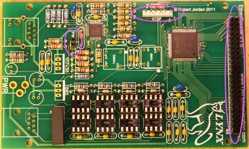
Install the 2 pin header next to the location labeled PWR.
Install the two 24 pin two row headers on the right side of the board. When installed they will form a single 48 pin header that, together with the power header, will accommodate future "daughter" boards that will expand the capabilities of the EtherDongle.
Install the 6 pin ICSP header at the top of the board. Make sure you put the small pins through the hole and point the longer pins up.
Solder all the headers.
Step 8 - Installing LED and Voltage Regulators
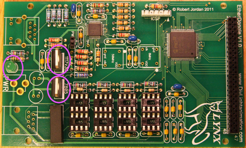
The LED is NOT a power indicator. Its a indicator that the pic is working and communicating
Install the green LED on the left side of the board. It is important to install the LED oriented properly. The LED will generally have one lead that is longer than the other. This is the positive (+) lead. The LED should be installed with the longer positive lead in the hole near the "+" label on the PCB.
There are two voltage regulators used on the board. One for 3.3V and one for 5V. Pay close attention to the installation of these parts so that you do not mix-up the two. You will damage the board if you install these incorrectly.
Install the 3.3V regulator (117v33) in the proper location making sure the metal back is aligned with the thick white line on the board (towards the right).
Install the 5V regulator (7805) in the proper location making sure the metal back is aligned with the thick white line on the board (towards the right).
Double check that you have the regulators in the proper locations and then solder them and the LED. Clip off the excess leads.
Step 9 - Installing the Voltage Regulator Heat Sink
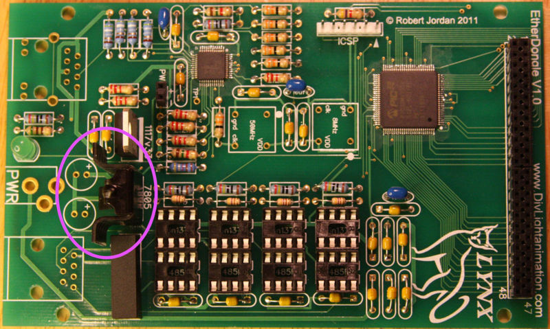
Slide the metal heat sink over the 7805 5V regulator as shown in the picture.
Step 10 - Installing the Ethernet, Power Connector, and RJ45 Jack
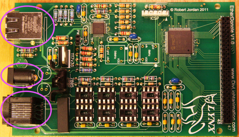
Install the silver "MagJack" Ethernet connector in the upper left side of the board. Note: that although there are 8 holes on the right side of that component area, the jack itself only has 7 pins in that area. So when you solder the component do not be concerned that one hole is missing a pin.
Snap in the RJ45 jack in the lower left side of the board.
Install the black power connector between the two jacks.
Solder the 13 pins on the Ethernet connector, the 8 pins on the RJ45 jack, and the 3 pins on the power connector.
Step 11 - Installing the Electrolytic Capacitors and Oscillators
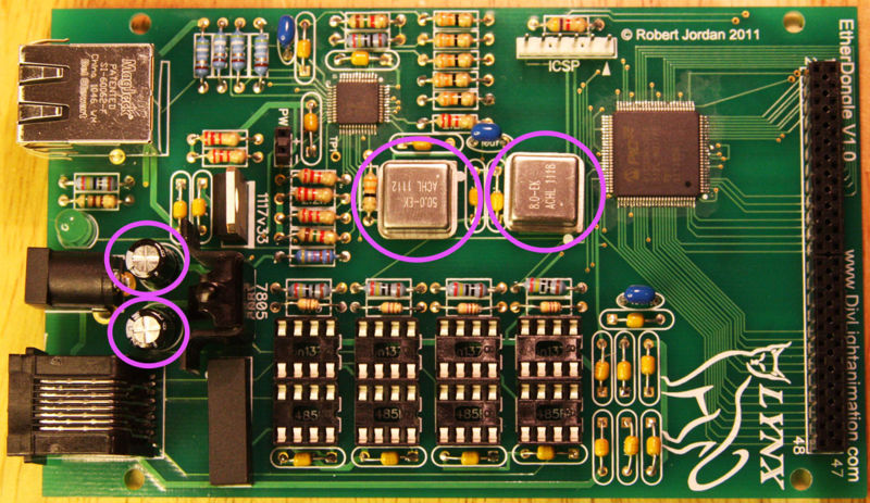
Install the two 100uF electrolytic capacitors on the left side of the board. Electrolytic capacitors are polarized and must be installed in the proper direction. Rotate the capacitor slowly while watching for the markings and graphical images on the capacitor. Some electrolytic capacitors will have only the negative side marked. The symbols will appear as ovals that look like minus signs (-), indicating the negative side of the capacitor. Some capacitors will have a white or a black stripe on the negative side. In such a case, the opposite side of the electrolytic capacitor is the positive side. If you cannot find the minus sign but you are able to see a plus sign (+), then the plus sign indicates the positive side and the other is the negative side. Make sure you install the positive lead in the hole indicated with with (+) sign.
There are two silver oscillators to be installed. They are NOT identical. Make sure you install the one marked 50.0 in the "50MHz" spot and the one marked 8.0 in the "8MHz" spot. The oscillators must also be oriented properly. You will notice a small dot on one corner of the component. This should line up with the white dot on the board. The corner with the dot will also have a square corner instead of rounded corners.
Solder the capacitors and the oscillators and trim leads as necessary.
Step 12 - Installing the IC Chips
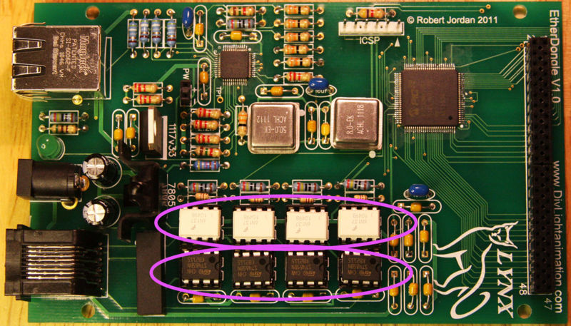
Install the four 6n137 optocoupler chips in the locations marked. Make sure you align the end of the chip with the small circle with the notched end of the socket. Be careful to not bend any pins under while pushing the chip in.
Install the four ST485BN chips in the locations marked. Make sure you align the notch on the end of the chip with the notch on the socket.
Programming The Lynx EtherDongle
In order to program the Lynx EtherDongle you must use the PICKIT3 versus the PICKIT2 used with all the other Lynx devices.
Connect the PICKIT3 to the computer via the USB cable. Plug in the PICKIT3 to the EtherDongle ICSP header, making sure you match the triangle marks on both the PICKIT3 and the EtherDongle board.
Start the PICKIT3 programming application. Select "PIC32MX795F512L" from the "Device:" drop down list. Select "File" from the tool bar and select "Import". Navigate to the location of the downloaded firmware and select the EtherDongle PixelNet or DMX .hex file. Click on the write button and once it completes, you may also press the "verify" button.