Difference between revisions of "Enttec Pro Connections"
| Line 16: | Line 16: | ||
* For the Light-O-Rama Equipment | * For the Light-O-Rama Equipment | ||
** XLR Pin 1 (GND) ----> N/C ? | ** XLR Pin 1 (GND) ----> N/C ? | ||
| − | ** XLR Pin 2 (-ve) ----> RJ45 Pin | + | ** XLR Pin 2 (-ve) ----> RJ45 Pin 5 (White/Blue) |
| − | ** XLR Pin 3 (+ve) ----> RJ45 Pin | + | ** XLR Pin 3 (+ve) ----> RJ45 Pin 4 (Blue) |
At the suggestion of "dr. jones" and referencing the Enttec manual, it appears that the output should be the female XLR connector, not the male connector. There was also a question of the pinout polarity. I have also added what should be the pinout to connect to LOR without an additional adapter. | At the suggestion of "dr. jones" and referencing the Enttec manual, it appears that the output should be the female XLR connector, not the male connector. There was also a question of the pinout polarity. I have also added what should be the pinout to connect to LOR without an additional adapter. | ||
Revision as of 01:55, 7 April 2009
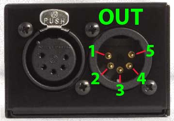
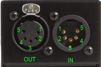
The Enttec USB Pro device has two ports, a male and female 5-pin XLR connector. For our purposes, the male connector (the one on the right) is what we will use to plug in our devices. The pinout is shown here:
Proposed update - please verify.
The following are the pinouts, assuming TIA-568B for the RJ45 end.
- For the Lnyx Equipment
- XLR Pin 1 (GND) ----> N/C
- XLR Pin 2 (-ve) ----> RJ45 Pin 2 (Orange)
- XLR Pin 3 (+ve) ----> RJ45 Pin 1 (White/Orange)
- For the Light-O-Rama Equipment
- XLR Pin 1 (GND) ----> N/C ?
- XLR Pin 2 (-ve) ----> RJ45 Pin 5 (White/Blue)
- XLR Pin 3 (+ve) ----> RJ45 Pin 4 (Blue)
At the suggestion of "dr. jones" and referencing the Enttec manual, it appears that the output should be the female XLR connector, not the male connector. There was also a question of the pinout polarity. I have also added what should be the pinout to connect to LOR without an additional adapter.
End proposed update
- Pins 1, 2, and 3 are the ones we want to use.
- Pin 1 = Ground
- Pin 2 = Signal -ve
- Pin 3 = Signal +ve
- These pin numbers are true for both 5-pin and 3-pin connectors, although strictly speaking 3-pin connectors should not be used as they don't comply with the official DMX512 standard.
- See here for more information
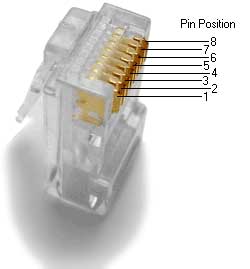
The Lynx devices use an RJ-45 plug instead of the more expensive XLR connectors. The pinout of an RJ-45 plug is shown here:
- Pins 1 and 2 are used here
- Pin 1 = Signal -ve (Goes to pin 2 on the XLR connector)
- Pin 2 = Signal +ve (Goes to pin 3 on the XLR connector)
- For CAT 5 Pinouts Wikipedia has a great little article and pictures.
Further information can be found at the Enttec website:


