3 Conductor
Contents
Connector Wiring: 3-Conductor
The purpose of this page is to share common wiring schemes for 3-conductor systems. As additional systems are added, please include them in a form in which others can benefit.
Information on 4-Conductor (4-core) wiring schemes can be found at 4_Conductor
3-Core Water-proof connectors
Water-proof connectors are available from Ray Wu, but they can also be purchased from US-based resellers (ask around for names). The following wiring scheme is offered as a standard to connect smart strings to a smart string controller (SSC). The original color assignments are taken from the wire colors used by an earlier 3-color pigtail -- which matched the colors used by the smart string pixels. Later 3-conductor pigtails use a different set of colors and must be converted to match the SAME pinouts used by the first generation. If DLA members use a common wiring standard, then old and new SSCs will be able to work with various string types. Further, kits assembled by other DLA members will be able to interoperate with kits from other DLA members. The chart below serves as a way to convert between old and new connector wire colors so that old and new connectors can be compatible as you add new devices to your display.
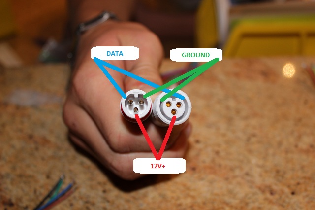
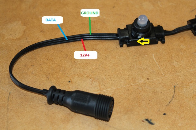
The picture below shows the pin assignments and the wire colors (1st-gen) and their use by a SSC:
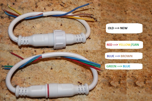
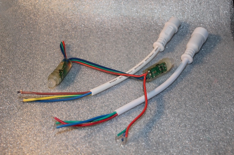
1st-gen wire colors are different from 2nd-gen colors. The picture below shows the conversion between the 2 colors. Substituting Yellow/Green for Red will pass 12V+, etc.
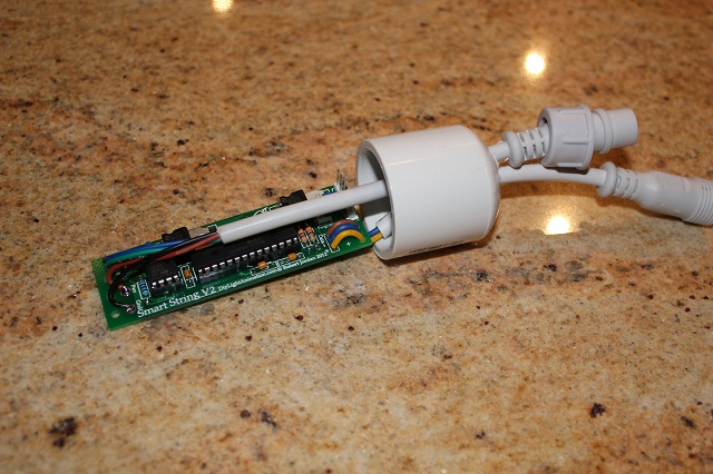
NOTE: When attaching a 3-core pigtail to the SSC PCB, you should use the female connector. A female connector will be less likely to cause a short because the pins are not exposed.
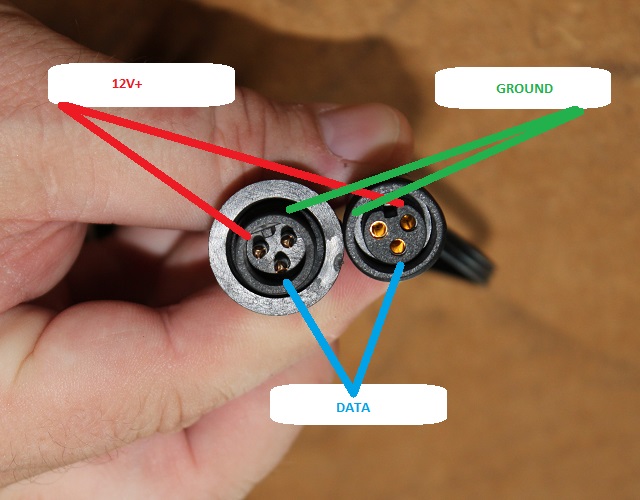
Waterproof SSC design using 3-core and 4-core connectors: Based on negative experiences with water and the SSC / RJ-45 pigtail design, an alteration has been suggested to use 4-core waterproof connectors in place of the RJ-45 pigtail.
The incoming cat5 cable must be altered to use a female 4-core pigtail in place of the normal cat5 plug. When modifying the cat5 cable, use the original twisted pair for the length of the cable, up to the pigtail... the twisted pair will allow the pin 1 and pin 2 pair to carry the signal for longer distances.
The SSC uses a male 4-core connector to receive the pixelnet with power from the smart string hub. The SSC then uses a female 3-core connector to send the smart string data and power to the string.
Table showing the smart string wiring as connected to the 3-core male connector. NOTE: always verify that the wiring has not changed, the manufacturer has changed color assignments in the past.
ORIGINAL 3-CORE SCHEME BASED ON OLD WIRE COLORS
| Old Ray Wu Connectors | Smart String | Flexible | Square Pixels | Rectangle | Rigid |
|---|---|---|---|---|---|
| +12v | Red | Red | Red | Red | Red |
| Ground | Green | Blue | Blue | Blue | Blue |
| Data | Blue | Green | Green | Green | Green |
| Current Ray Wu Connectors | Smart String | Flexible | Square Pixels | Rectangle | Rigid |
| +12v | Yellow/Green-stripe | Yellow/Green-stripe | Yellow/Green-stripe | Yellow/Green-stripe | Yellow/Green-stripe |
| Ground | Blue | Brown | Brown | Brown | Brown |
| Data | Brown | Blue | Blue | Blue | Blue |
| Connectors | Old Ray Wu | Current Ray Wu Connectors | |||
| +12v | Red | Yellow/Green-stripe | |||
| Ground | Green | Blue | |||
| Data | Blue | Brown |
TECHNICOLOR SCHEME
| Connectors | Old Ray Wu | Current Ray Wu Connectors |
|---|---|---|
| +12v | Green | Blue |
| Ground | Blue | Brown |
| Data | Red | Yellow/Green-stripe |
